 Transmitter Package 01PM Drawing
Mechanical line drawing of the 01PM telemetry transmitter package (chassis), including dimensions and connector pin numbering.
 20 Jul, 2026
  83.19 KB
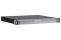
Transmitter Package 01PM Model
STEP (ISO 10303-21) 3D model of the Quasonix 01PM telemetry transmitter package (chassis) exterior.
20 Jul, 2026
1.00 MB
ISO 9001:2015 Certificate (Moorpark)
Certificate showing assessment of the Quasonix Moorpark facility's Quality Management System by Eagle Registrations, Inc. and conformation to the ISO 9001:2015 standard.
13 Jul, 2026
352.91 KB
Quality Management System Documentation
Overview of our quality policy and the systems, processes, and management that support it.
 5.11
27 Jun, 2026
553.29 KB
5.11
27 Jun, 2026
553.29 KB
Rackmount Transmitter Platform Drawing
Mechanical line drawing of the Quasonix Rackmount Transmitter Platform, with dimensions. Includes rear panel / connectors.
8 Jun, 2026
254.28 KB
TMoIP Processor Standard Letter of Volatility
Quasonix TMoIP Processor memory/media overview. Telemetry data is processed in volatile SDRAM and is never stored in non-volatile memory.
8 Jun, 2026
472.46 KB
Transmitter Binary Protocol Manual
The binary serial protocol is designed to facilitate efficient machine to machine communication. This manual defines the binary protocol version 1.009.
4.0.4
8 Jun, 2026
660.46 KB
Maximum Likelihood Stream Combiner (MLSC™) Manual
Installation and operation of the Quasonix Maximum Likelihood Stream Combiner (MLSC™) - a better Best Source Selector.
1.0.3
8 Jun, 2026
2.53 MB
ISO 9001:2015 Certificate (West Chester)
Certificate showing assessment of the Quasonix West Chester facility's Quality Management System by Eagle Registrations, Inc. and conformation to the ISO 9001:2015 standard.
1 Jun, 2026
296.13 KB
 RDMS™ Rackmount Receivers
 RDMS™ Rackmount Receivers
 The Third-Generation Quasonix RDMS™ Rackmount Receiver delivers market-leading telemetry performance in a compact, highly configurable 1U package.
20 May, 2026
RDMS™ Binary Interface (Gen 3, R19.3) (Download)
Describes the machine UART interface for Quasonix RDMS receiver bricks. Includes a description of the binary protocol; binary tag IDs; and examples.
19.3
30 Mar, 2026
20.86 KB
MLSC and BSSA Standard Letter of Volatility
Memory and media present in the Quasonix Maximum Likelihood Stream Combiner (MLSC™) and and the Quasonix BSS Analyzer (BSSA™).
30 Mar, 2026
282.06 KB
Receiver Analyzer Model (Download)
STEP (ISO 10303-21) 3D model of the Quasonix RDMS™ Receiver Analyzer.
27 Mar, 2026
1.72 MB
Receiver Analyzer Drawing
Mechanical line drawing of the Quasonix RDMS™ Receiver Analyzer.
27 Mar, 2026
115.59 KB
Receiver Analyzer Quick-Start Guide (Gen 3)
Quick-Start installation instructions for the third-generation rackmount Quasonix Receiver Analyzer.
27 Mar, 2026
1.14 MB
Receiver Analyzer Manual (Gen 3)
Installation and operation of the third-generation rackmount Quasonix Receiver Analyzer, which includes a powerful new user interface.
1.0.2
27 Mar, 2026
12.53 MB
Receiver Analyzer
 Receiver Analyzer
 The Receiver Analyzer automates a wide range of receiver and combiner performance tests. RA 3.0 software improves flexibility, speed, and time savings.
27 Mar, 2026
Receiver Analyzer Manual (Gen 2)
Installation and operation of the second-generation rackmount Quasonix Receiver Analyzer.
2.5.9
27 Mar, 2026
4.61 MB
TIMTER™ Transmitter Manual
Installation and operation of Quasonix’s TIMTER™ Multi-mode Digital Telemetry Transmitters.
3.9.21
27 Mar, 2026
4.11 MB
TIMTER™ Dual Transmitter Manual, Firmware v2
Installation and operation of Quasonix’s TIMTER™ Multi-Mode Dual Telemetry Transmitters, firmware version 2.xxx (required for transmitters with the -D2 option). Find firmware version with VE command or in startup banner.
1.5.17
27 Mar, 2026
5.16 MB
TIMTER™ Dual Transmitter Manual, Firmware v1
Installation and operation of Quasonix’s TIMTER™ Multi-Mode Dual Telemetry Transmitters, firmware version 1.xxx. Find firmware version with VE command or in startup banner.
1.6.19
27 Mar, 2026
5.06 MB
nanoTX™ Transmitter Manual
Installation and operation of Quasonix’s nanoTX™ and nanoPuck™ Multi-Mode Digital Telemetry Transmitters.
3.4.20
27 Mar, 2026
4.24 MB
GMLRS Transmitter Manual
Installation and operation of Quasonix’s GMLRS multi-mode digital telemetry transmitters.
1.3.20
27 Mar, 2026
3.03 MB
Transmitter Pinout NE
Connectors and their pin assignments for Quasonix telemetry transmitter pinout code NE.
26 Mar, 2026
66.01 KB
Transmitter Pinout M8
Connectors and their pin assignments for Quasonix telemetry transmitter pinout code M8.
26 Mar, 2026
144.98 KB
Transmitter Package 06BE Model
STEP (ISO 10303-21) 3D model of the Quasonix 06BE telemetry transmitter package (chassis) exterior.
26 Mar, 2026
568.80 KB
Transmitter Package 06BE Drawing
Mechanical line drawing of the 06BE telemetry transmitter package (chassis), including dimensions.
26 Mar, 2026
100.64 KB
Rackmount Receiver 3U with -IP2 Option – Drawing
Mechanical line drawing of the Quasonix RDMS™ 3U Rackmount Receiver with -IP2 Option (supports publishing the payload data as IP packets IAW IRIG 218-20).
26 Mar, 2026
162.35 KB
Rackmount Receiver 3U with -IP2 Option – Model (Download)
STEP (ISO 10303-21) 3D model of the Quasonix 3U Rackmount Receiver with -IP2 Option (supports publishing the payload data as IP packets IAW IRIG 218-20).
26 Mar, 2026
10.29 MB
Precision Drive™ HyperTrack™ Antenna Periodic Maintenance Log
Instructions necessary for monthly inspection, preventive and corrective maintenance, and alignment of the antenna system in accordance with warranty requirements. This form/log is to be executed monthly and sent to Quasonix to maintain the warranty agreement.
24 Mar, 2026
158.53 KB
RDMS™ Receiver Standard Letter of Volatility (Gen 3)
This document describes the memory and media present in all Quasonix RDMS™ third-generation receivers and notes that payload data cannot be stored in the RDMS™ itself, nor can it be routed to other devices on its Ethernet network.
20 Mar, 2026
149.38 KB
RDMS™ Receiver Standard Letter of Volatility (Gen 2)
This document describes the memory and media present in all Quasonix RDMS™ second-generation receivers.
20 Mar, 2026
19.15 KB
 Privacy Policy
 Privacy Policy
 This page describes our practice of minimizing the collection of personal information and our policies for keeping collected data secure and private.
19 Mar, 2026
Terms of Service
This page describes visitors' responsibilities when using this website and limits on Quasonix's liability.
19 Mar, 2026
Disclaimer
Information regarding Quasonix's ownership of the content of this site, our effort to keep the site up to date and safe, and limits on our liability.
19 Mar, 2026
 Home
Home
 Home
Home Reinventing Telemetry® With a razor-sharp focus on aeronautical telemetry, powered ... Read more
19 Mar, 2026
DQM and RDMS™ Troubleshooting Guide
Introduction to the Data Quality Metric and its role in troubleshooting, and an essential troubleshooting flowchart for Gen 3 RDMS™.
17 Mar, 2026
500.83 KB
QTrack™ Antenna Quick-Start Guide
Quick-Start installation instructions for the Quasonix QTrack™ antenna, including hardware setup, IP camera setup, and Quasonix receiver configuration. For use with QTrack™ HyperTrack™ systems.
1.0
17 Mar, 2026
1.31 MB
QTrack™ Antenna Firmware Update Procedure
Instructions for updating the firmware and client of the Quasonix QTrack™ antenna. For use with QTrack™ HyperTrack™ systems.
1.0
17 Mar, 2026
920.99 KB
QTrack™ Antennas
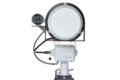 QTrack™ Antennas
 Quasonix QTrack™ portable low-gain antennas, coupled with industry-leading Quasonix RDMS™ telemetry receivers, are the perfect solution for portable or mast-mounted antenna applications. Watch a short demo!
16 Mar, 2026
Receiver and Transmitter Terminal Software
A simple serial port (COM) terminal emulation program used for serial communication with Quasonix products.
1.9b
17 Feb, 2026
277.24 KB
Rackmount Receiver 1U Drawing
Mechanical line drawing of the Quasonix RDMS™ 1U rackmount receiver exterior (chassis), including dimensions and back-panel connectors.
17 Feb, 2026
922.45 KB
Quasonix Catalog
Catalog of Quasonix's full product line including transmitters, antennas, receivers, networking equipment, and test equipment. Also includes examples of possible product configurations.
17 Feb, 2026
16.30 MB
RDMS™ Compact Receiver Datasheet (Gen 3)
Features, specifications, options, and possible band configurations for Quasonix's third-generation compact (airborne) RDMS™ telemetry receiver.
16 Feb, 2026
548.79 KB
Transmitter Package 07BF Drawing
Mechanical line drawing of the 07BF telemetry transmitter package (chassis), including dimensions.
11 Feb, 2026
Transmitter Package 07BF Model
STEP (ISO 10303-21) 3D model of the Quasonix 07BF telemetry transmitter package (chassis) exterior.
11 Feb, 2026
3 MB
Transmitter Package 21AA Drawing
Mechanical line drawing of the 21AA telemetry transmitter package (chassis), including dimensions and connector pin numbering.
11 Feb, 2026
Transmitter Package 07AD Model (< 1 MB Download)
STEP (ISO 10303-21) 3D model of the Quasonix 07AD telemetry transmitter package (chassis) exterior.
11 Feb, 2026
<1 MB
Transmitter Package 00AA Drawing
Mechanical line drawing of the 00AA telemetry transmitter, including dimensions.
11 Feb, 2026
Transmitter Package 01AB Drawing
Mechanical line drawing of the 01AB telemetry transmitter package (chassis), including dimensions and connector pin numbering.
11 Feb, 2026