

Catalog of Quasonix’s full product line including transmitters, antennas, receivers, networking equipment, and test equipment. Also includes examples of possible product configurations.
Fourth-Generation Powerhouse
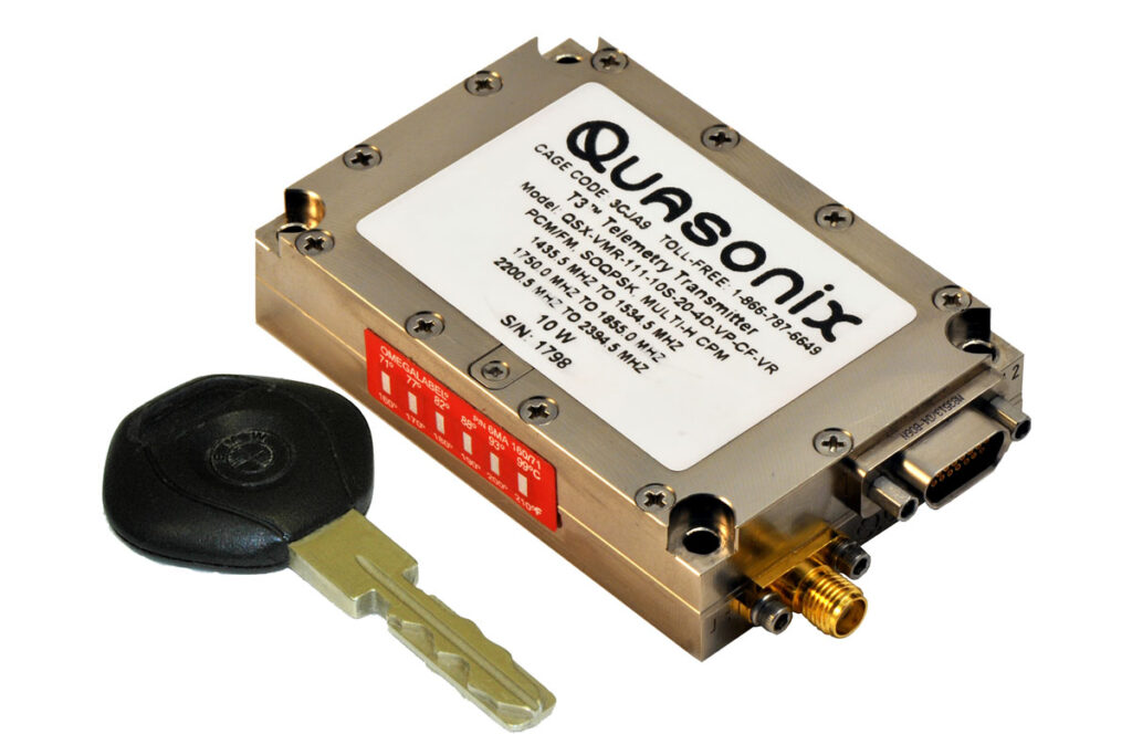
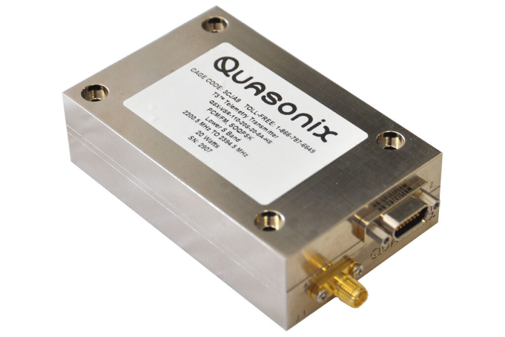
Quasonix digital multi-mode telemetry transmitters are the benchmark of the industry, providing unparalleled performance and value in small, robust, power-efficient packages. We offer proven quality, with over 17,000 transmitters shipped.

Take Your Telemetry to the Next Level—Even the Moon
A Quasonix TIMTER transmitter supported the first U.S. soft lunar landing in over 50 years, demonstrating outstanding efficiency and performance under extreme conditions.
Upgrade to the Industry’s Preferred Transmitter
Quasonix fourth-generation transmitters take the industry standard to the next level with higher efficiency, better cooling, lower phase noise, lower harmonics, and more.

Power Up with Exceptional Efficiency
Already the most efficient transmitters in the field, our latest models now deliver 20 W of output without exceeding the current draw of older 10 W units.

Deploy with Confidence
Built to last and engineered for performance, Quasonix transmitters deliver the rugged reliability your mission demands.

Find the Perfect Transmitter for Your Mission
With broad frequency, power, and modulation capabilities—plus dozens of options like LDPC coding and variable power—Quasonix has the right transmitter for you.
Documents
TIMTER™ Transmitter Datasheet
Features, options, specifications, and select accessories for Quasonix’s range of multi-mode telemetry transmitters, including nanoTX™ and nanoPuck™.
Receiver and Transmitter Low-Density Parity Check Datasheet
The Low Density Parity Check (LDPC) Forward Error Correction mode improves link margin equivalent to nearly tripling the operating distance on your telemetry link.
SOQPSK with LDPC ITC Paper
“SOQPSK with LDPC: Spending Bandwidth to Buy Link Margin,” by Terry Hill & Jim Uetrecht; presented at ITC 2013.
TIMTER™ Transmitter Manual
Installation and operation of Quasonix’s TIMTER™ Multi-mode Digital Telemetry Transmitters.
3.9.21
4.11 MB
GMLRS Transmitter Manual
Installation and operation of Quasonix’s GMLRS multi-mode digital telemetry transmitters.
1.3.20
3.03 MB
JF-12 Files (1 MB Download)
These files address the applicability of the US Government’s JF-12 and DD Form 1494 classification documents to Quasonix’s TIMTER™ transmitter product line.
1 MB
Transmitter Configuration with STC and LDPC (Download)
This brief presentation provides flowcharts and diagrams to help clarify transmitter configuration with Space-Time Coding (STC) and Low-Density Parity Check Coding (LDPC)
<1 MB
Receiver and Transmitter Low-Density Parity Check Guide
This technical guide introduces Low-Density Parity Check (LDPC) encoding, its uses and benefits, the Quasonix products it is available for, and considerations for optimal set-up and use.
1.1.1
Transmitter Binary Protocol Tester Manual
How to test the binary protocol of Quasonix telemetry transmitters using Binary Protocol Tester software provided by Quasonix.
1.0.4
Transmitter Binary Protocol Manual
The binary serial protocol is designed to facilitate efficient machine to machine communication. This manual defines the binary protocol version 1.009.
4.0.3
IRIG 106-13, Appendix N Interpretation
Explains Quasonix’s standard transmitter protocol and how transmitters with the C7 option (IRIG 106-07 control protocol) will behave differently.
1.2
Transmitter RF Troubleshooting Guide
Quick, three-part test to verify that the RF output on a Quasonix telemetry transmitter is working correctly.
1.2
Transmitter Overtemp Control Guide
How to modify the internal overtemperature (OT) setting using the OC command. This applies to all Quasonix telemetry transmitters.
1.0
Receiver and Transmitter Terminal Software
A simple serial port (COM) terminal emulation program used for serial communication with Quasonix products.
1.9b
277.24 KB
Transmitter Binary Protocol Tester Software
Software (bintest.exe) for testing the binary protocol of Quasonix telemetry transmitters connected to PC via serial port.
1.029
<1 MB
Transmitter Get Info Software
Free Quasonix utility that collects diagnostic information from a transmitter via a serial connection to a computer.
1.004
<1 MB