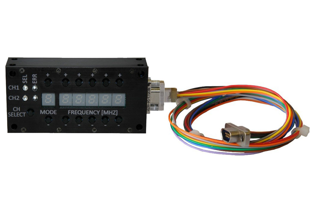
While the TIMTER™ provides a standard configuration interface that is easily accessible via a computer terminal, some users prefer configuration via an external switch box. The 2nd Generation Quasonix switch box, used with the P9 option, provides six LED digits used to display the mode and frequency. This includes a total of five digits of frequency step up or down, in MHz, and one digit of mode selection in terms of the ARTM “Tier” number. There is also a channel selector for channel 1 or channel 2 when connected to a Dual Telemetry Transmitter. An 18” MDM-9 to MDM-9 cable harness is included.
Part Number: QSX-AC-DSWBX
User Manuals and Guides
| Type | Title | Version | File Size | Updated | Length | Description |
|---|---|---|---|---|---|---|
| Transmitter Switchbox Manual (Gen 1) | 1.4.1 | 2019.08.05 | How to set up and use the legacy frequency and mode switchbox for TIMTER™ transmitters. | ||
| Transmitter Switchbox Manual (Gen 2) | 1.3.3 | 2021.02.04 | How to set up and use the second-generation digital frequency and mode switchbox, released in 2018, for TIMTER™ transmitters. |

