
Catalog of Quasonix’s full product line including transmitters, antennas, receivers, networking equipment, and test equipment. Also includes examples of possible product configurations.
Ultimate Bitstream Accuracy Starts Here
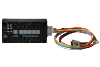
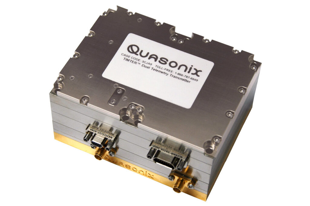
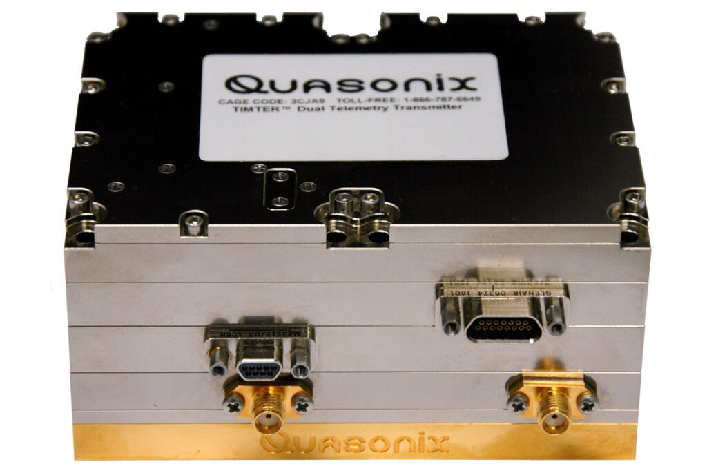
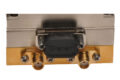
Quasonix digital multi-mode dual telemetry transmitters provide the flexibility of two high-
performance, independent transmitters in one package.

Choose the Industry’s Only Dual Transmitter
Quasonix is the only manufacturer offering a transmitter engineered specifically for STC and dual-antenna telemetry applications.

Maximize Link Resilience with True STC Support
Purpose-built for Space-Time Coding and frequency diversity—delivering robust performance in dynamic RF environments.

Customize Each Channel to Your Mission
Independently configure frequency, modulation, and output power per RF channel for maximum operational flexibility.
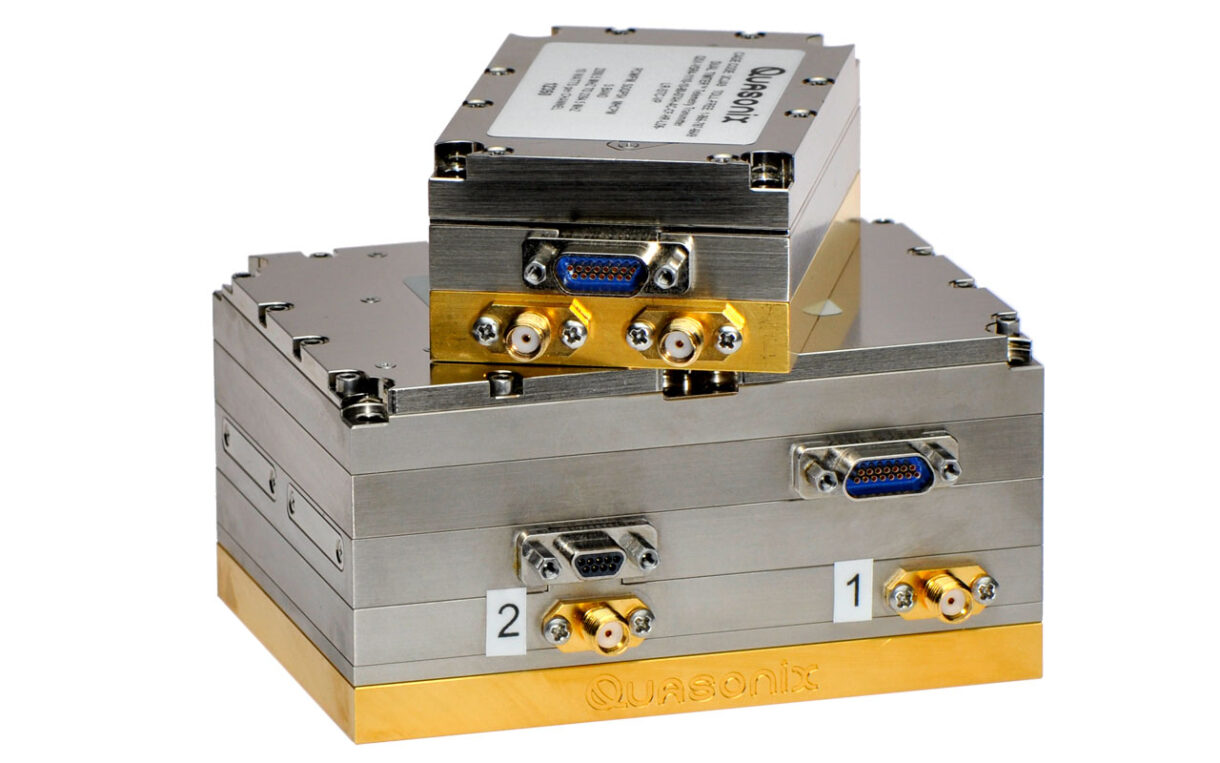
Minimize SWaP, Not Capability
High RF performance in a lightweight, space-saving form factor—ideal for airborne and space-rated applications.

Trust a Solution Proven in Flight
Rugged and flight-qualified for demanding test ranges, including high vibration, altitude, and temperature extremes.
Documents
TIMTER™ Dual Transmitter Datasheet
Features, popular options, and specifications for Quasonix’s dual telemetry transmitters, which optionally support Low-Density Parity Check (LDPC) Coding and are Space-Time Coding (STC) capable.
Receiver and Transmitter Space-Time Coding Datasheet
The Quasonix Space Time Coding Solution eliminates link outages caused by the “two-antenna problem,” improving behavior of received signal power and overall link availability.
Receiver and Transmitter Low-Density Parity Check Datasheet
The Low Density Parity Check (LDPC) Forward Error Correction mode improves link margin equivalent to nearly tripling the operating distance on your telemetry link.
Space-Time Coding ITC Paper
“Space-Time Coding Solution to the Two-Antenna Interference Problem,” by Mark Geoghegan & Louis Boucher; presented at ITC 2014.
SOQPSK with LDPC ITC Paper
“SOQPSK with LDPC: Spending Bandwidth to Buy Link Margin,” by Terry Hill & Jim Uetrecht; presented at ITC 2013.
TIMTER™ Dual Transmitter Manual, Firmware v2
Installation and operation of Quasonix’s TIMTER™ Multi-Mode Dual Telemetry Transmitters, firmware version 2.xxx (required for transmitters with the -D2 option). Find firmware version with VE command or in startup banner.
1.5.17
5.16 MB
TIMTER™ Dual Transmitter Manual, Firmware v1
Installation and operation of Quasonix’s TIMTER™ Multi-Mode Dual Telemetry Transmitters, firmware version 1.xxx. Find firmware version with VE command or in startup banner.
1.6.19
5.06 MB
JF-12 Files (1 MB Download)
These files address the applicability of the US Government’s JF-12 and DD Form 1494 classification documents to Quasonix’s TIMTER™ transmitter product line.
1 MB
Transmitter Configuration with STC and LDPC (Download)
This brief presentation provides flowcharts and diagrams to help clarify transmitter configuration with Space-Time Coding (STC) and Low-Density Parity Check Coding (LDPC)
<1 MB
Receiver and Transmitter Low-Density Parity Check Guide
This technical guide introduces Low-Density Parity Check (LDPC) encoding, its uses and benefits, the Quasonix products it is available for, and considerations for optimal set-up and use.
1.1.1
Transmitter Binary Protocol Tester Manual
How to test the binary protocol of Quasonix telemetry transmitters using Binary Protocol Tester software provided by Quasonix.
1.0.4
TIMTER™ Dual Transmitter Manual (Legacy)
Installation and operation of Quasonix’s Legacy Dual Telemetry Transmitters.
1.3.6
Transmitter Binary Protocol Manual
The binary serial protocol is designed to facilitate efficient machine to machine communication. This manual defines the binary protocol version 1.009.
4.0.3
IRIG 106-13, Appendix N Interpretation
Explains Quasonix’s standard transmitter protocol and how transmitters with the C7 option (IRIG 106-07 control protocol) will behave differently.
1.2
Transmitter RF Troubleshooting Guide
Quick, three-part test to verify that the RF output on a Quasonix telemetry transmitter is working correctly.
1.2
Receiver and Transmitter Terminal Software
A simple serial port (COM) terminal emulation program used for serial communication with Quasonix products.
1.9b
277.24 KB
Transmitter Binary Protocol Tester Software
Software (bintest.exe) for testing the binary protocol of Quasonix telemetry transmitters connected to PC via serial port.
1.029
<1 MB
Transmitter Get Info Software
Free Quasonix utility that collects diagnostic information from a transmitter via a serial connection to a computer.
1.004
<1 MB
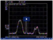
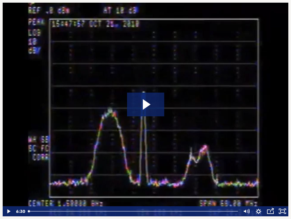
STC vs. Traditional Two-Antenna Solution
Recording from an early test flight showing how Space-Time Coding (left haystack) eliminates signal fades inherent in a normal two-antenna solution (right haystack). Quasonix offers a range of dual transmitters specially designed for STC. All third-generation Quasonix rackmount receivers are STC-capable, provided that ARTM Tier I demodulation (SOQPSK-TG) is optionally enabled.
(Used in TM Smorgasbord training, Day 3.)